When I bought Britannia it didn't have any engine room ventilation fans or even natural aeration with cowls.

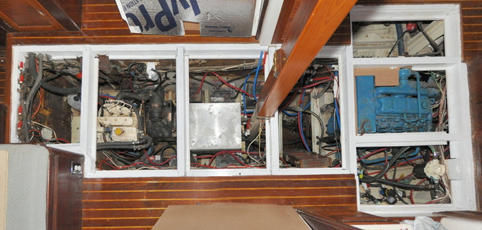
equipment -bayHRThe term “engine room” is a bit misleading on my boat because the area is 26’ feet long, from the forward saloon bulkhead to the stern gland. It is also 4’6” inches down to the bottom of the bilge. This cavernous area doesn't just contain the large Perkins 4-236 main engine, but all the other machinery that runs the boat, including a diesel generator, a water heater, nine batteries, a large battery charger and five electric pumps. All these form what I call the “equipment bay.” When everything is humming, and especially when both the generator and main engine are running together the heat permeating though the 3/4” inch plywood cabin sole could be felt on bare feet. I once placed a thermometer in the space and after five minutes it registered 150F, that isn't good for the machinery or our feet.
Whether you have a large underfloor area or a small engine compartment, it will always be beneficial to ventilate the space. All mechanical devices create heat and diesel engines are designed to run hot, but internal combustion engines always run better when drawing cooler air that has the effect of increasing the swept volume in the cylinders.

It was obvious to me that a single electric fan would be hard pressed to suck all the hot air out and draw cooler air in over such a long area. I thought about whether to have two fans sucking air out, but theoretically that would require a larger inlet. Ideally, a fan would be needed to blow fresh air into the front of the compartment, and one to suck the hot air out, somewhere near the stern. Since the floorboards are not air-tight I was also a bit concerned that air might be sucked down from the air conditioned living areas. The ACs work full-time as it is and I didn't want to make it any harder.

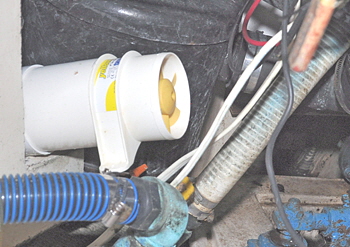
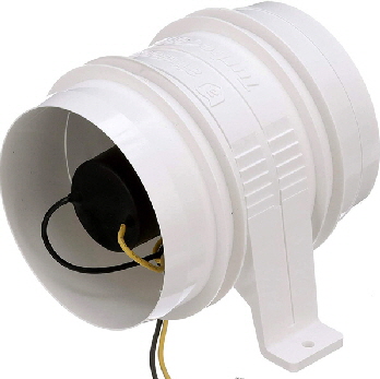
I then had to decide how to route trunking from on deck to below the floorboards, yet maximize the air flow. I found a 4” inch diameter, five blade fan on Amazon.com, for $35.00. The Attwood 1749-4 Turbo 4000 is a 12-Volt in-line blower designed to fit 4” Inch interior diameter piping. The specification said it was water resistant and guaranteed for three years.

I wondered how to route the trunking to achieve maximum flow, and indeed what type of trunking to use. Large flexible plastic wire wound pipe is frequently used on boats for air conditioning, but my experience has been that even if the pipe is protected from vibration through bulkheads, where it inevitably needs to pass, it only takes one small tear in the plastic sheathing to cause a leak and reduce the air flow. Sometimes a leak can't even be seen and usually gets worse as time goes by. Furthermore, because this type of piping is so thin walled it conducts heat very easily, but my objective was to get the heat out of the boat, not to warm the various lockers the pipe passed through. I found 4” inches diameter corrugated aluminum pipe in my local hardware store that is stronger than flexible plastic, but also conducts heat even more. Any flexible pipe can easily be squashed by other items moving about in lockers, sometimes severely limiting air flow.

Showing how the pipe was routed from the deck to the equipment bay.After much thought and lots of measurements, I finally decided to use 4” inch diameter rigid plastic pipe, the type used in houses as sewage lines. This has a wall thickness of about 1/8” inch and is smooth bored offering the least resistance to air flow. 90°degree and 45° degree bends are also available enabling a pipe to be routed just about anywhere. Rigid pipe is also self supporting over quite a long distance between bulkheads. I bought three 10’ lengths and some different bends because with this type of project it's difficult to know what bends will actually be needed, so being able to return the unused ones to the store was a great advantage.

This is the hole cutter used to get the 4" pipes through bulkheads.At the forward end of the equipment bay was a bank of six vertical lockers. Ideal to route a long inlet vent pipe straight down from on deck to the forward end of the bay. It was almost as though they were built for the job. However, what I didn't count on was the effort needed to cut the large diameter holes, first through the deck then through seven more thicknesses of 3/4” inch solid teak. It was very hard going, using a 4 1/4” inch diameter hole cutter on a right angled drill attachment, slowly boring through each locker base then finally through the lower bulkhead into the equipment bay. It was tricky to get the holes exactly level, so the extra 1/4” inch gave me some wiggle room. I was finally able to slide a 10’ foot long pipe straight through all the holes, then, using a 90° degree bend on the end, air was directed straight on to the generator motor. Not many boats will have such a convenient way to install an inlet pipe, but it doesn't need to blow into the center, anywhere at the front of your engine area will do
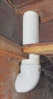
The down pipe directs air into the equipment bay directly on to the generator.I left the pipe sticking out of the deck an inch, so I needed some type of vent cover to stop rain entering the pipe, yet still with good air flow. I thought that a classic Dorade style vent, where air has to pass over a baffle might restrict the maximum air the fan could draw. So I made a much simpler box with baffles to keep rain water out, yet still allow good air flow.  I also mounted the fan half way down the tube, in a locker big enough to be able to get at it in the event it might fail. When the locker doors are closed nobody would ever know there is a large ventilation pipe inside.

This vent allows maximum air, but does not allow water.The pipes and bends slotted perfectly into each other and into the fans with an airtight fit. I didn't want to actually glue the pieces together because there is always a chance of something breaking, so dismantling any section would be easier if it was not glued. I simply drilled a hole through a joint, then screwed a self tapping screw in to stop them coming apart through vibration. One disadvantage of using rigid pipe, especially 4” inches diameter is that it is sometimes difficult to pass long lengths through lockers and bulkheads, because it can't be bent. The way round this is to use a coupling and splice two sections of pipe together, after they are fitted in both bulkheads. I also had to use a short length of flexible aluminum tube to negotiate a tight bend.

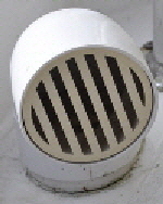
Flexible pipe allowed for some awkward routing.I positioned the rear fan alongside the main engine, so it would suck the maximum amount of hot air out. There was only one way the tubing could then be routed to the back of the boat, through the aft cabin starboard lockers and up to the aft deck. I cut the holes with my hole cutter and drill, that were by now beginning to show signs of fatigue, as were my arms and shoulders. It took a lot of scrambling through lockers and bulkheads to get the rear piping lined up, but eventually, using both 90° and 45° degree bends, I managed to bring the pipe out through a hole in the deck. I then caulked it and used a 90° degree bend and grating to act as a cowl. I also bought a cap that fitted on the pipe, to keep rain out when we were not using the blowers.

The outlet cowl in the stern can be closed-off when not needed.There is no on/off or reverse switch on these fans and to reverse the air flow the fan is just mounted in the opposite direction. Wiring them was also easy, by connecting to spare 12-volt contact breakers on the main distribution panel, that I marked, “extractor fans.” I wasn't concerned about current draw either because I only use the fans when the engine or genny are running, both of which have alternators.

This is the rear fan, used to extract the engine smells.When I first switched both fans on an enormous rush of air shot out the rear cowl like a jet engine and I had visions it might give us at least another knot? The real test however was how much the system would displace the hot air and reduce the temperature in the bay, when everything was operating normally. For that test I ran the two diesels until the temperature had risen to 150F, then switched the fans on. The heat coming out of the rear vent would have melted varnish! It still took fifteen minutes to drop the temperature to 100F and a further fifteen to reduce it to 85F. Then I started the fans when the engines were cold the temperature remained steady at near the ambient outside temperature and the generator runs cooler when the blower is on. In Florida, where I live, even blowing 95° air in is cooler than normal running temperatures and I could almost hear the equipment breathing a sigh of relief

There was another unexpected benefit I had not considered. The air rushing out of the rear vent smelled of a machine shop, so the fans were also removing odor that would normally congregate in the equipment bay. Whenever I arrive at the boat I now switch both fans on immediately I open up and they seem to help remove that “closed up boat smell,” quicker.
This was a very satisfactory outcome for all the effort and not much actual cost. It would be a worthwhile addition to any boat, especially one with all the machinery like Britannia.


Fans-header
Back to navigtion
Two large extractor fans clear the equipment bay.