There can be few instruments more important on a boat than that which shows the amount of fresh water in the tanks. If there is one thing you need to know on a cruising boat, especially if it doesn't have a water-maker, it is an accurate indication of how much drinking water you have. Over the years that I have owned Britannia, I have expended endless hours and patience messing about trying to get the original twin water tank gages to register correctly.

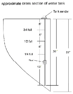
Section drawing of the  tanks from which the senders were calibrated.Britannia has two stainless steel water tanks amidships, one each side. The shape follows the curve of the hull and is therefore somewhat triangular in cross section, tapering to a point at the base. This makes accurate calibration of any type of measuring system difficult, because when the water is half way down the vertical side of the tank, the actual capacity is much less than half full, in fact only about 1/3rd full. This physical fact would even apply to the simplest method of measuring water capacity - and probably the most reliable - where the level is read from a transparent sighting tube up the outside of the tank.

I considered fitting these external tubes, but since my tanks are enclosed by bulkheads all round I couldn't easily drill a hole in the bottom of the tanks to install plumbing fittings and a clear plastic tube. Even if I had managed to fit a sighting tube in each tank I still would have had to physically calibrate the tube at various capacity levels. Also, to read a sighting glass would also mean lifting the floorboards on each side every time.

These were the original instruments,The original system was, (note the past tense), pneumatic, i.e. air operated, that was supposed to read the air pressure differential as the water level in the tanks varied. Basically it is a simple concept having only two components and no electrics. Just the job for a cruising boat you might think.

A rigid plastic pipe mounts vertically inside the tanks, from the top to the bottom, (at least, that's what I thought I had), and is connected to a gage by a thin flexible nylon tube. As the water level varies in the tank the pressure changes in the pipe and the tube, and is registered on the gage. The system never worked properly from the day I bought the boat. The gage would frequently drop to zero, sometimes immediately after a tank was filled to the top, or sometimes slowly over a few days. The whole thing was erratic and unreliable, due I think to air leaks.

Since there are no electronics involved I reasoned that there had to be an air leak somewhere, probably in the connections between the tank pipe and the gage, or even in the gage itself. I therefore sealed the connections with epoxy, but still the gages failed. I then took the back off the gages and examined the delicate clock-like mechanism in minute detail. I tightened up the tiny diaphragm mounts and inspected the moving parts, all to no avail. I also conducted numerous water tests by immersing everything in a bathtub, looking for air bubbles to identify a leak. Finally I even submerged the gage itself but no air leaks were visible. To make a diagnosis even more difficult, the original manufacturers had long gone, and nowhere to be found on the Internet. The chances of finding any information, help or spare parts was therefore slim. To cut a long frustrating story short; I never did find out why the system didn't work properly. So finally I decided to look for a reliable alternative, then junk the whole lot.

The shape of the tanks meant that a simple electrical swing arm float would not register accurately anyway, because when the arm is half way on its ark and the gage registers half full it will not be correct. There was also a baffle in my tank that obstructed a swing arm system anyway.

The tops of the new gauges fitted in the original holes. There is a product called The Tank Tender, that works on the same pneumatic principal as my original equipment. To overcome tank shape problems their gage is calibrated in inches of water and It is for the user to determine how many inches corresponds to any particular capacity. The manufacturers told me that most owners mark their gages with an ink marker at the quarter, half and three quarters point. This would be accurate, but from my experience I was concerned about pressure leaks in any air system. I would also have to buy two gages, one for each tank and the cost would be about $570

I then found an electrically operated device that also uses a vertical tube in the tanks, but instead of working on air pressure it has a float that travels up and down the tube, activating electrical signals inside the stainless steel tube that are then read by the gage. The sender tube's top flange fitting also matched the standard SAE (Society of American Engineers), five hole pattern in the top of my tanks, so I would not have to drill and tap any new mounting holes. It is made by Wema/Kus USA. Fort Lauderdale, Florida. www.wemausa.com/sensors/level-FuelWater

The technical department were extremely helpful and told me they could actually custom calibrate the tank tube to my exact tank shape. All they needed was a drawing showing where the various water levels were in the tank corresponding to full, 3/4, 1/2 and empty. This would ensure the gage read the correct capacity of water in the tank throughout the whole range.

the Kus system also has a duel gage mounted on a single panel with a switch to read either port or starboard tank. Switching to one side, the gage reads from one tank and from the other it reads from the other tank. In the middle the switch is off and no electric current is being used. However, for this gage to register accurately for twin tanks, both sides have to be the same shape, that mine are. The gage also lights up when reading a tank and there is a choice between red and yellow illumination.

The first test I needed to do was to find out exactly how much water the tanks actually held. I drained both sides by running all the water out through the boats faucets, then re-filled them one at a time using a flow meter fitted to the water hose. I bought this from Amazon.com for $14.96 (part # P3-P0550 ). The actual capacity turned out to be 168 US gallons each side, eight more than the makers specification. This gave a total capacity of 336 US gallons, which is 268 Imperial UK gallons or 1272 liters.

A water flow meter will give an accurate reading of the amount of water flowing though.   To find out exactly how long the new tank sender pipes needed to be I removed the old tube and measured the depth with a length of 1/4” inch diameter wooden dowel. This read 31” inches to the bottom of the tanks, but the sender tube would not fit to the bottom of the tank because of the curvature, so I settled for 29”inches. This was when I realized the original 21” inch long tubes could never have registered accurately anyway, even if they worked properly, because they were 8” inches too short and never reached anywhere near the bottom of the tank. I calculated this produced an error of about 25 gallons in each tank.

Having determined the capacity I drained the tanks once more and took the opportunity to flush them with two gallons of swimming pool chlorination liquid from a local pool supply shop. I then ran 42 gallons into the tanks, this being one quarter of the total capacity, then physically measured the water level with my wooden dipstick that I only lowered 19” inches into the tank. Then I added another 42 gallons and measured where half full actually was, then another 42 to bring the capacity to three quarters. I put these dimensions on my drawing, that I e-mailed to the Kus engineers.

I received my kit in two weeks.

I drained the tanks once more, then lowered the starboard tank sender tube through the hole in the top of the tank. This was when I discovered that the standard SAE five hole plate does not have symmetrical holes round the top of the plate, even though it looks like they are equally spaced. There is in fact only one position the plate can be fitted, and to find this you have to rotate the plate and gasket until the holes all line up with the screw holes in the tank. I kept loosing the location of the gasket and plate, until I actually glued the gasket to the top of the tank then rotated the plate to mate with the existing holes in the top of the tank. There must be a reason why they didn't make the holes equally spaced, but I don't know what it is.

After I finished the starboard side, another problem arose with the port tank. I found that the hole in the top of this tank had been cut 4”  inches further into the tank than on the starboard tank. This meant that the calibrated tube would be even shorter than the port side and not go anywhere near the bottom of the tank. I decided to cut a new mounting hole.

Drilling holes in the new location was tricky, because I wanted to ensure the minimum amount of swarf from the drill fell into the water tank. As I drilled each hole I positioned my vacuum near the bit, that sucked up most of the filings. I used a new 1 1/4“ inch diameter hole cuter to cut the center hole for the float to pass through, then I lowered the sender into the tank and used the top as a guide to drill a hole through one of the five bolt holes. I tapped this hole with a 5/64” inch thread and screwed the plate tightly in place. This ensured the other four holes would not move and remain accurately positioned. I then drilled and tapped these and secured the unit. I then made a plate from some 1/8” thick stainless steel to plug the old hole and after drilling the holes I screwed and caulked it in place to seal the hole.The tank gauge reads both side tanks separately by swithing from one to the other.

The gage was much easier to fit, but needed more than the regular round hole to mount it. It is more like a square hole that I cut by making a template out of paper and sticking it in place with Scotch tape, then drilling the corners and cutting  between them with a keyhole saw. The wiring was easy and I ran the power through a spare contract breaker on the master panel.

It was then just a matter of refilling the tanks in one quarter increments using my flow meter and checking the gage registered correctly, which it did right through to completely full.

Of course, one also has to be aware that the reading from any tank system, including even a simple sighting tube, will be incorrect when a sailboat is under sail and heeled. I suppose the only remedy for this would be gimbaled tanks, right!

The diagram of wiring the new system. The total cost for two sender tubes and the duel gage panel was $320. But if you are content to mark the face of the gage as you fill the tanks you could just buy a standard system with your appropriate tube lengths, (sold in one inch increments). The price would then be less than my custom calibrated model.

Kus also make a similar system for fuel tanks, because the same capacity problem exists when diesel tanks are also the shape of the hull. At least, when running an engine the consumption can be estimated by knowing the fuel/hours ratio, that is not so for fresh water consumption.

It is now a great relief to know I have a reliable record of water capacity for each tank. This enables us to maximize and enjoy the usage, according to whatever passage we are making.
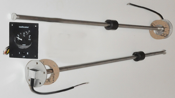
 

These are the sender tubes for the water tanks and the gauge which reads both side tanks.

INSTALL AN ACCURATE FRESH WATER GAUGE

Return to the articles gallery here.