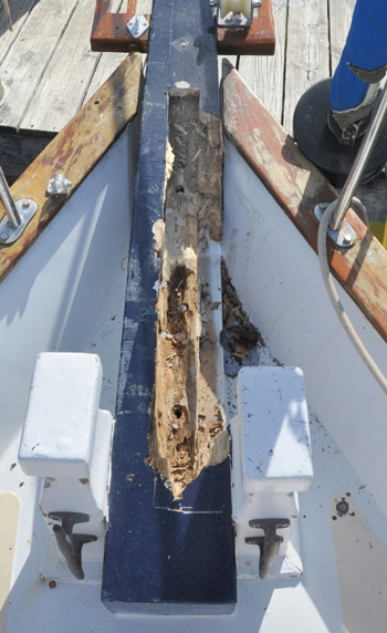
 The first indication there was any problem with Britannia’s bowsprit was when I was hoisted up the foremast using the electric windlass that is bolted on top of the bowsprit. The operator mentioned the windlass “moved” as the load came on the winding drum. When I came down the mast I saw what he was talking about, because the windlass was slightly out-of-square on the bowsprit. Clearly something was amiss, although I couldn't see anything wrong with the painted wooden bowsprit. I checked the four bolts securing the windlass through the deck and they were nicely tight.
It then didn't take but a few minutes probing with a screwdriver to realize there was a serious soft wood rot problem beneath the windlass. I removed the four long securing studs and brought a load of rotten wood out with them. Further scouring with a chisel and electric cutter revealed extensive rot in the long bowsprit.
At first I hoped it would be possible to repair the ‘sprit in situ, by scarfing some new planks in to replace the damaged ones. But that was ruled out as I scoured more and more soft wood from the interior of the spar, and I gave up after a length of 38” inches! Clearly the boat needed a complete new bowsprit, either made of wood like the existing one, or perhaps metal.
The spar was a tapered lamination of nine sections glued together. It measured nine feet six inches long, eight inches square at the heel, and five inches square at the crance iron.
Other owners told me how their bowsprits were constructed, but they were all different with no consensus as to how strong a replacement needed to be. Surely some said, it made sense to make another in wood like the old one. What they didn't know was that the previous owners log showed a new bowsprit had been installed in 2005, that did not persuade me towards a third wooden spar. If I was to make a new bowsprit in anything other than wood it had to be at least as strong as the previous one.
 When analyzing forces on a bowsprit there are a number of factors to consider. When under sail there is an upwards and sideways pull on the spar by the jib that varies depending on the point of sailing, the wind strength, and of course the size of the head sail. This pressure is resisted mainly by the bobstay and in Britannia’s case also a dolphin striker that transmits some load into the bow and the bowsprit shrouds. Obviously, the actual strength of the bowsprit itself and how it is secured to the bow is also crucial. If all fittings are correctly tensioned the opposing forces result in a mainly compression force, pushing the bowsprit backwards.
These interactions would be fairly easy to calculate in a simple static force diagram, but a boat under sail is hardly a static force and a major unknown factor is when the bow ‘scends’ into a head sea, plunging the complete pulpit into solid water. This imposes goodness knows what loads on the whole pulpit structure and nobody, including a sailboat architect could tell me what these might be.
A friend loaned me Skene’s elements of yacht design. This had a small section on bobstays but surprisingly, nothing about bowsprits. It does include the sentence, ”Since impact loads like head seas cannot be determined accurately, most designers apply a factor of three to five in their estimates.” That struck me as a pretty wide margin, and in other words it was all based on experience, or perhaps destruction tests, none of which was helpful to me.
ALTERNATIVES AND ESTIMATES 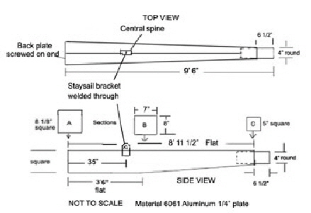 I made a drawing of the existing bowsprit and sent it to three wooden boat builders who all said they could “easily” make one in Douglas Fir. However, on seeing “The complexity of the job” one declined to quote and then came the next shock! One quote was $2875.00 and the other $3278.00! Apparently the wood had to be shipped from the Pacific North West, about as far as it could be from Florida where Britannia lay. Also, no actual time for completion was even mentioned by either builder, although I specifically asked for it. It was obvious that none of these people really wanted the job.
My next option was to see if I could buy the wood myself. I located a lumber supplier in Minnesota who quoted $830.00 for four 2” inch thick ten feet long and eight inches wide finished straight grained planks of Douglas Fir.
Building the thing myself would of course be the cheapest way, but a daunting task. First I would have to glue and clamp the planks together, then shape the heavy log, weighing about 200 lbs and as big as a railroad tie into a taper with a 4” inch perfectly round section on the end to carry the crance iron. Furthermore, all this would have to be done with hand tools in my garage in Orlando, then carted back and finished off outside at the dock. I have undertaken some big projects on Britannia, like completely changing the rig from a ketch to a schooner, rebuilding the generator in situ, and building a squaresail, but this project was just too much for me to consider.
I decided to explore the possibility of having the ’sprit fabricated in aluminum. After researching different types of aluminum plate I decided that 1/4” inch thick type 6061 structural aluminum would be suitable. This is as hard as nails and much stronger than regular aluminum. I didn't consider stainless steel on the grounds of cost and weight. Luckily for me, my son-in-law is a patent attorney in New York, a job that requires a high degree of engineering qualifications and Jim offered advice on the aluminum design.
The bowsprit needed to be the same outward shape and size as the existing spar, so that all fittings would bolt back in the same place. I therefore designed a box section with a vertical central spine all the way along the inside. This formed an ‘I’ (eye) beam that is a well known section for stiffness in both bending and compression. I was also interested in the weight of aluminum against timber. Kiln dried Douglas Fir weighs roughly 35 lbs per cubit foot, and I calculated my existing spar was 3.24 cu ft. That made it about 113 lbs. The weight of 1/4” inch thick 6061 aluminum sheet is 3.56 lbs per square foot, and I worked out the square footage of each piece in the design, that all added up to 27.83 sq ft. and a weight of 99 lbs, including a round block at the tip to carry the crance iron.
Two aluminum fabricating companies gave me quotes. One was $1525.00, including powder coating painting the bowsprit and crance iron. The other quote was $2200.00 in raw form. It won't be difficult for experienced boat owners to guess which was the ‘marine’ fabricators quote, as opposed to a regular welding company near Orlando, Florida.
After further discussions with Jim I decided to have the new bowsprit made in aluminum and I gave the job to Twin City Welding in St Cloud, near Orlando. David Lucey, the owner, had done small jobs for me before and I knew the excellent quality of their welding. They also stocked the sheets and were very familiar with the welding characteristics of 6061. Another advantage was that they could start the job almost immediately. I therefore decided not to remove the old bowsprit until the new one arrived.
CONSTRUCTION.
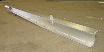 After all the pieces had been sheered out of a 10’ x 4’ foot aluminum sheet, the top and bottom sections were welded to the center spine. The bottom had been tapered slightly to form the underneath towards the tip. A new forestay bracket was also welded through a slot in the top plate. The original stainless steel bracket was bolted through the deck, so my design avoided two more holes through the deck.
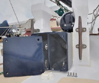 A 4” inch diameter tube was welded on the tip to carry the heavy bronze crance iron that weighed 26 lbs. on its own.
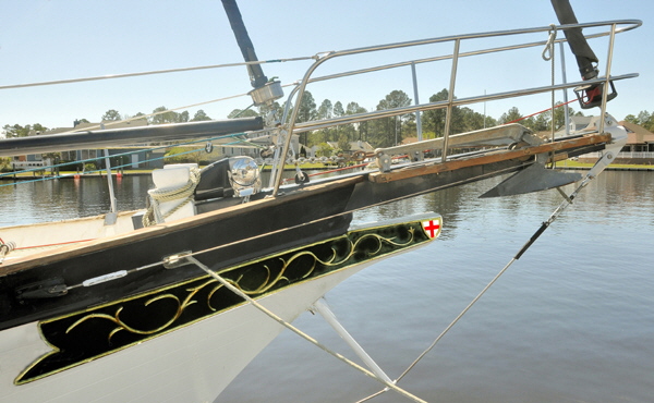
The two sides were then welded to the top and bottom to complete the box section. This resulted in a very stiff spar and after it had been powder coated it looked magnificent in its new dark blue livery, to match the other spars. The new bowsprit arrived exactly two weeks from placing the order and weighed 96 lbs., I was 2 lbs. out in my calculation.
I designed the heel plate to be screwed on the end of the bowsprit and removable so I could reach through to bolt it to the two Samson posts. (bitts). I drilled two 3/8” inch holes in the bottom near the heel plate to drain any water that might find its way into the interior.
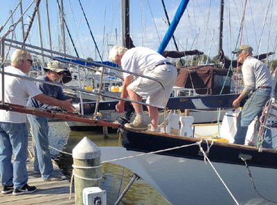
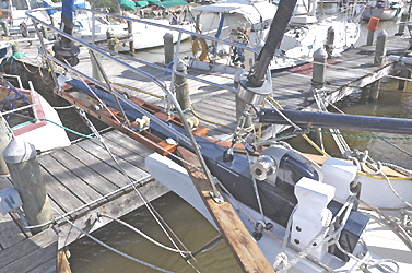
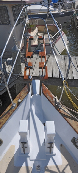 When ready to make the exchange of bowsprits I supported the pulpit and grating with ropes from the foremast, that saved removing these cumbersome items. Next I withdrew the eight long threaded rods that held the pulpit and grating through the old bowsprit, along with the threaded rods holding the bowsprit to the deck and Samson posts. Then, with a few willing helpers the damaged bowsprit was levered clear from the bow and pulpit. Britannia looked very forlorn without her majestic ‘sprit, that adds character to any clipper bow.
The wooden bowsprit weighed 116 lbs, allowing for the missing rotten sections and I was 3 lbs heavy with that calculation. I cleaned up the stem-head, filled all the old holes and re-painted the area, We were now ready to install the new bowsprit.
REINSTALLING.
With help from the same mates who lifted the old spar, we offered the new bowsprit into its seat and I was relieved to find it fitted perfectly. Then the Maxwell windlass was positioned on top of the bowsprit with bolts through previously drilled holes, straight through the deck. This pulled the bowsprit down on the deck and secured it. Three heavy 2/0 AWG electrical wires for the windlass motor also came up through the hollow structure.
Holes were then piloted sideways though the Samson post bolt holes and both posts bolted from inside the tube. The gratings and pulpit were then re-positioned and holes piloted through from both sides and bolted together using the old 3/8” inch stainless threaded studs. I replaced the threaded studs that carried the two bow rollers with solid rods, but before reinstalling the actual bronze bow rollers I drilled a 1/4” inch hole through one side to the middle, then tapped it to take a grease nipple. This would allow for occasional oiling of the rollers. I screwed a blank thread in the hole to stop dirt entering as the dirty chain was hauled up from anchoring.
The crance iron that had been powder coated white was pushed on its tube and the jib stay, fore-stay, bobstay and shrouds relocated and tensioned. Both anchors were then hauled back into their rollers. I had to make twelve 1” inch teak plugs and six 1 1/4” inch plugs to fill the holes in the grating and Samson post. I made these by hand because I didn't have a plug cutter for those sizes.
The reassembly operation took three days, and all this heaving and maneuvering was done with the boat in the water and the bow sticking over the dock. This was easier and cheaper than lifting the boat, because we didn't need scaffolding or ladders, as we would have on the hard. But I was very grateful for the help of three fellow boat owners and without their help it would have been impossible for me to do the job alone.
I now wondered how I might test the new structure. The ultimate test of course would be a sea trial in heavy weather but I also decided to conduct a simple static test, by bowsing the bowsprit down to see what happened.
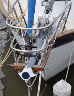 I wanted to test the strength and security of the bowsprit alone, not the jib and staysail stays, so I disconnected them both. With only the bobstay and shrouds attached to the crance iron I lowered the 60 lbs CQR over the bow roller and hooked it under the large marina dock-beam directly below. Then I measured the distance from the crance iron to the dock.
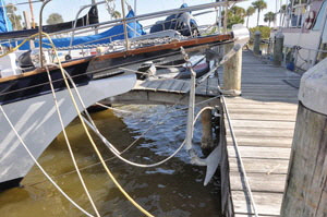 I began to tension the chain with the windlass that I was pleased to see never even moved on its mount. This hauled the bow downwards and the bobstay bracket disappeared under water. A second touch on the windlass hauled the bow down further and the chain became bar tight. Amazingly, the bobstay also remained taught, and it would have gone slack if there had been any bending in the bowsprit. Another touch on the windlass button resulted in ominous groans from the dock timbers, so I quickly measured the drop then slacked it all off. The bowsprit had been dragged down 7” inches. Hauling a beamy boat like Britannia down this far displaces a considerable weight of water and imposed some impressive loads on the bowsprit, but there was absolutely no evidence of movement or paint chipping anywhere along the new bowsprit.
On seeing the finished result Jim wrote, “Based on the back of the envelope calculations I did and your test, I think your new bowsprit is anywhere from five to ten times stiffer than Douglas Fir, and can probably withstand a load at least five times greater before yield or fracture”. This was good to hear from a highly qualified engineer
By way of a post-script: Some time later I learned about the boat in the next marina to mine that had serious rot in the bowsprit. It was a Hanz Christian double ender of about the same vintage as Britannia. I told the owner about my experience and he also had a new bowsprit built by David Lucey in St. Cloud.
All’s well that end's well.
BUILDING A NEW BOWSPRIT
If you have a problem
doing this article you can email Roger here. CONTACT